Welcome to my HAM Radio Blog.

As a passionate HAM radio operator, I, Daniel Dibbets, proudly operate under the callsigns DL6FZ and AF6FZ. These two identifiers represent my dedication to the art and science of amateur radio communication, serving as a bridge between communities, frequencies, and enthusiasts around the globe.

Whether engaging in DXing, sharing knowledge, or participating in contests, I am committed to fostering global connections, advancing technical innovation, and contributing to the rich tradition of amateur radio. Operating with DL6FZ and AF6FZ allows me to connect with fellow operators across different bands and regions, embodying the spirit of curiosity and collaboration that makes HAM radio so rewarding.

Join me on the airwaves as I continue to explore new frequencies, share experiences, and expand the horizons of HAM radio under the callsigns DL6FZ and AF6FZ!

Kind regards and 73s,
Daniel de DL6FZ / AF6FZ

Posted in Uncategorized | Comments Off on Welcome to my HAM Radio Blog.

M17 Analog Hotspot Gateway, a surprising Amazon find ?!

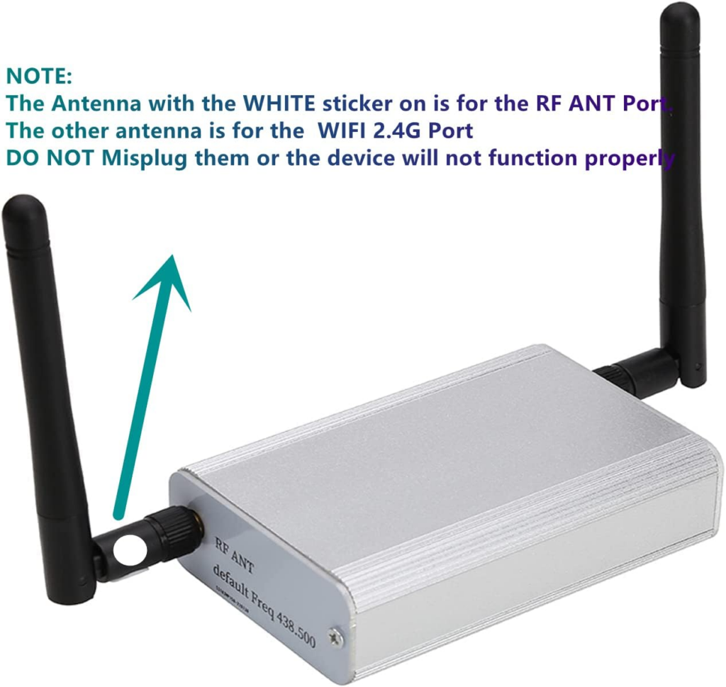
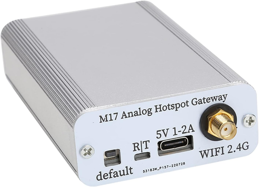
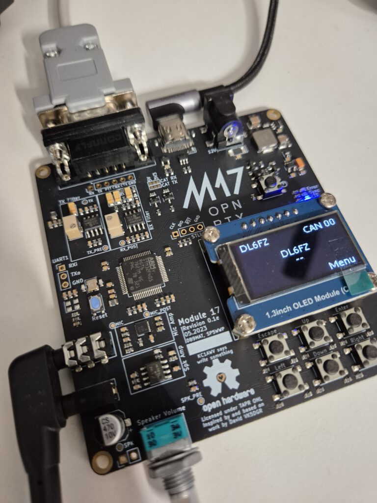
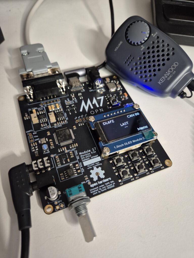
Sometimes you stumble on weird things on Amazon, in my case an M17 Analog gateway for about €40 from Amazon Germany shop.

Curious on this device, and simply also somewhat surprised to find a M17 gateway on Amazon I ordered this end of last week and got it delivered today.

Its a really funky device, that works actually quite well. Please see the pictures below and the nice article from VK4PK

Glenn Lyons VK4PK, wrote a very nice web-page on this gateway..

https://www.lyonscomputer.com.au/Digital-Modes/M17/M17-Analog-Hotpot-Gateway/M17-Analog-Hotpot-Gateway.html

Posted in Digital Modes (VHF/UHF), M17 | Comments Off on M17 Analog Hotspot Gateway, a surprising Amazon find ?!

Tuning the bandpass filters on an Icom commercial mobile radio..

.. is actually pretty cool. Is it magic? 🙂

Posted in Icom IC-F610, VHF/UHF Transceivers | Comments Off on Tuning the bandpass filters on an Icom commercial mobile radio..

Calibrating a Radio Duplexer Using a Vector Network Analyzer (VNA)

Purpose:

Calibrating a radio duplexer ensures optimal performance by minimizing insertion loss, maximizing isolation, and maintaining proper frequency separation between the transmit (TX) and receive (RX) paths.


Equipment Required:

  1. Vector Network Analyzer (VNA)
  2. Calibration Kit (with open, short, and load standards)
  3. RF cables (high-quality, low-loss, and matched for your frequency range)
  4. Adapters (if required, to connect the VNA to the duplexer)
  5. Duplexer (with TX, RX, and antenna ports)

Step-by-Step Process:

1. Preparation:

  1. Check Equipment: Ensure the VNA and calibration kit are functioning properly. Verify the frequency range of the VNA covers the duplexer’s operational band.
  2. Warm-Up: Turn on the VNA and allow it to warm up for 15–30 minutes to stabilize its internal components.
  3. Inspect Connections: Examine the RF cables and connectors for damage or contamination. Clean the connectors if necessary.

2. Configure the VNA:

  1. Frequency Range: Set the frequency sweep range on the VNA to cover the duplexer’s operational band (including TX and RX passbands and stopbands). Recommended spans are 350 MHz–500 MHz for 70 cm and 100 MHz–250 MHz for 2 m.
  2. Number of Points: Select a sufficient number of frequency points (e.g., 401 or higher) for accurate measurements.
  3. IF Bandwidth: Adjust the intermediate frequency (IF) bandwidth for a balance between noise reduction and measurement speed (e.g., 1 kHz).

3. Perform Calibration:

  1. Select Calibration Type: Use a 2-port or 3-port calibration based on the number of ports being measured simultaneously.
  2. Connect Standards: Perform a full 2-port calibration by sequentially connecting the calibration kit’s open, short, and load standards to the VNA ports. Follow the VNA’s on-screen prompts.
  3. Thru Calibration: Connect the RF cables directly (thru configuration) to calibrate the VNA’s response with minimal insertion loss.
  4. Verify Calibration: After calibration, check the results by measuring a known device (e.g., a termination or filter) to ensure the VNA is properly calibrated.

4. Connect the Duplexer:

  1. Identify Ports: Label the TX, RX, and antenna ports on the duplexer.
  2. Connect to VNA:
    • TX Port to Port 1: Connect the TX port of the duplexer to Port 1 of the VNA.
    • Antenna Port to Port 2: Connect the antenna port to Port 2.
    • RX Port: Terminate the RX port with a 50-ohm load to ensure proper impedance matching and prevent reflections during measurement.

5. Measure and Adjust:

  1. Insertion Loss (TX Path):
    • Measure the S21 parameter to assess the insertion loss from the TX to antenna port.
    • Adjust tuning screws or elements in the duplexer (if available) to minimize insertion loss.
  2. Isolation (TX to RX):
    • Swap the VNA connections to measure S12 or S21 between the TX and RX ports.
    • Adjust the tuning to maximize isolation.
  3. Repeat for RX Path:
    • Connect the RX port to Port 1 and the antenna port to Port 2.
    • Measure the insertion loss (S21) and isolation (S12). Adjust accordingly.

6. Fine-Tuning:

  1. Alternate between measurements for the TX and RX paths, fine-tuning each until specifications are met.
  2. Verify the duplexer’s frequency response matches the required passband and stopband characteristics.
  3. Avoid Over-Tight Calibration: When tuning, do not calibrate the duplexer too sharply; instead, set it slightly wider to account for potential temperature-based calibration fluctuations.

7. Final Verification:

  1. Test Return Loss: Measure the return loss (S11) at each port to ensure good impedance matching. Aim for at least -15 dB return loss.
  2. Save Data: Store the VNA measurement data for documentation and future reference.

Tips:

  • Use high-quality cables and connectors to minimize measurement errors.
  • Avoid overtightening or cross-threading RF connectors.
  • If your VNA supports time-domain analysis, use it to locate and diagnose any discontinuities or mismatches in the duplexer.

Safety Note:

Always handle RF equipment with care and ensure the duplexer is not connected to any active transmitter during calibration.

Posted in Test Equipment, Vector Network Analysers | Comments Off on Calibrating a Radio Duplexer Using a Vector Network Analyzer (VNA)

MD-380 Volume Control Modification for OpenRTX/M17

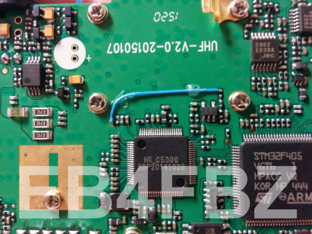
Today I performed the MD-380 Volume Control Modification for OpenRTX/M17 on one of my MD-380 radios.

This was to try to get the audio level improved for M17, after updating the radio with OpenRTX.

https://github.com/OpenRTX/OpenRTX/issues/266

I did the mod as described here:

https://github.com/travisgoodspeed/md380tools/issues/98

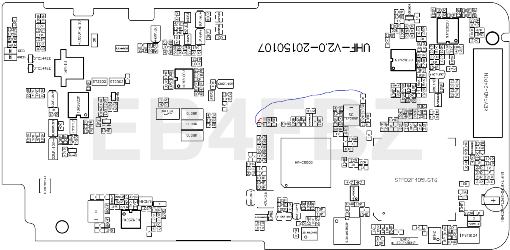
This will make the volume control work again after flashing the MD-380 with OpenRTX. Unfortunately the audio level did not improve – the max is still quite low. I guess we’ll have to wait untill the audio-path going through the HR_C5000 is implemented.

Thanks to EB4FBZ for the great explanation on how to do this;

Remove R341 (100K) and connect the signal to VOL_OUT (R253) using a 47K resistor and wrapping cable.

Posted in Digital Modes (VHF/UHF), M17, TYT MD380, VHF/UHF Transceivers | Comments Off on MD-380 Volume Control Modification for OpenRTX/M17

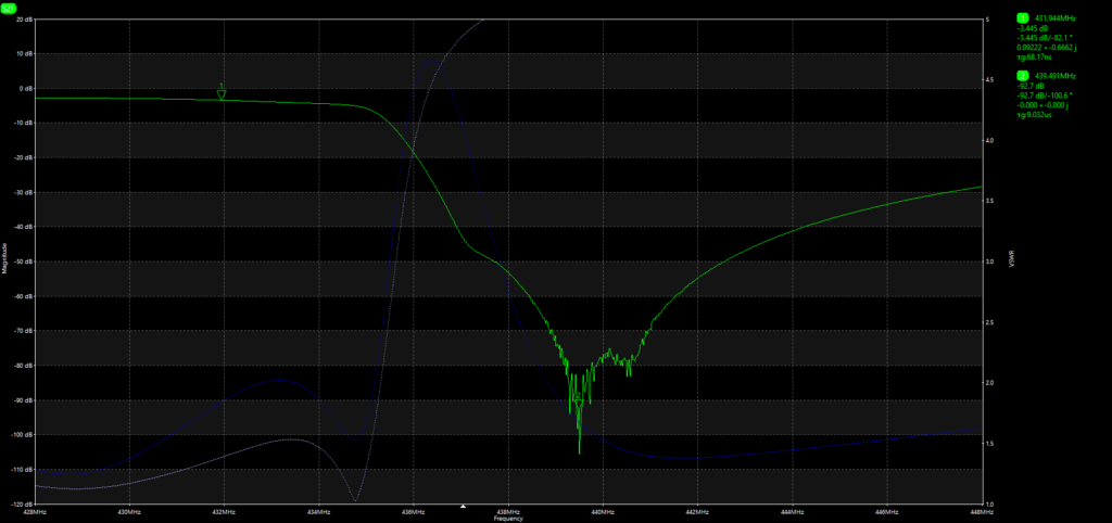
Happy happy. With my new Vector Network Analyser: the LibreVNA

After having used the amazing VNWA3SE Automatic 2 Port VNA from DG8SAQ for several years now, I needed an upgrade to be able to better calibrate my antenna duplexer.

After reasearching quite a bit I found the LibreVNA, a 100khz-6Ghz VNA with a dynamic range of ~ 100dB also designed as an OpenSource project here in Germany by Jan Käberich

I ordered one from the great guys at Eleshop.de and got it delivered to my home within 2 days!

I’ve been working and learning with this VNA now for a few days and I just love it.

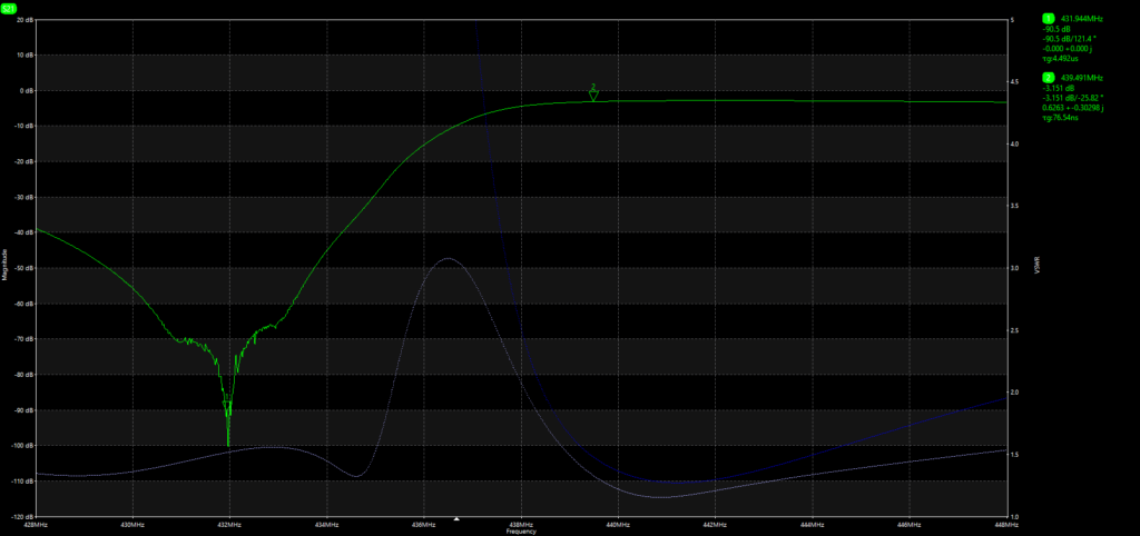
Here are 2 examples of tuning a duplexer for my new M17 / DMR Multimode repeater DB0FZ:

Posted in Test Equipment, Vector Network Analysers | Comments Off on Happy happy. With my new Vector Network Analyser: the LibreVNA

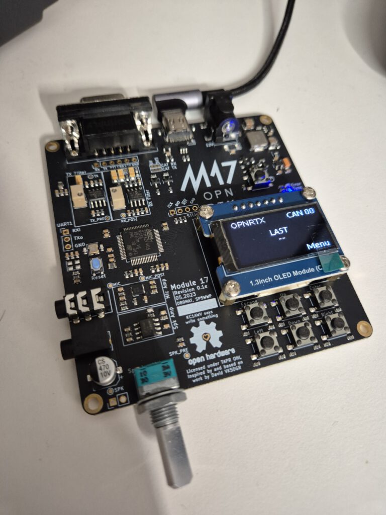
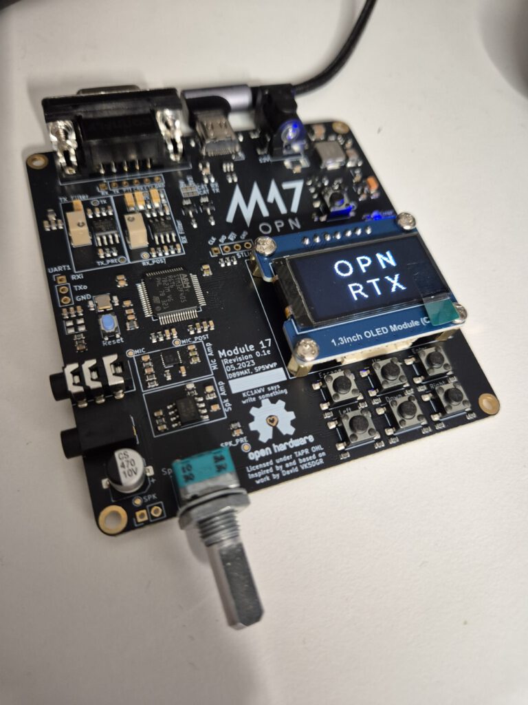
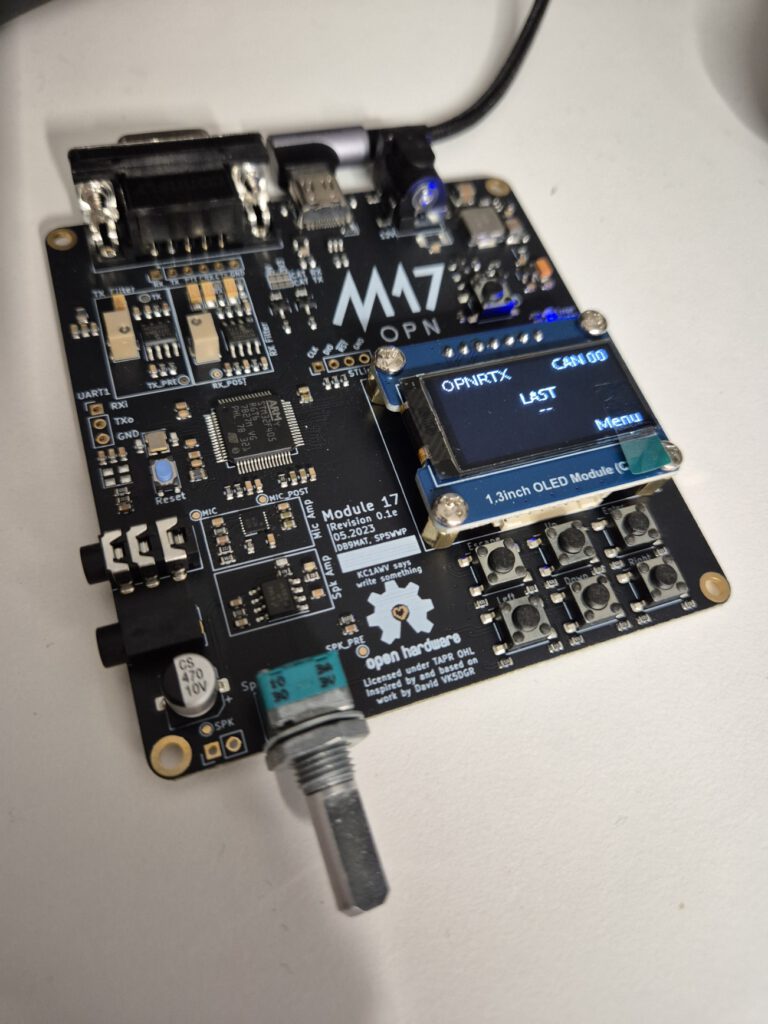
My new M17 Module17

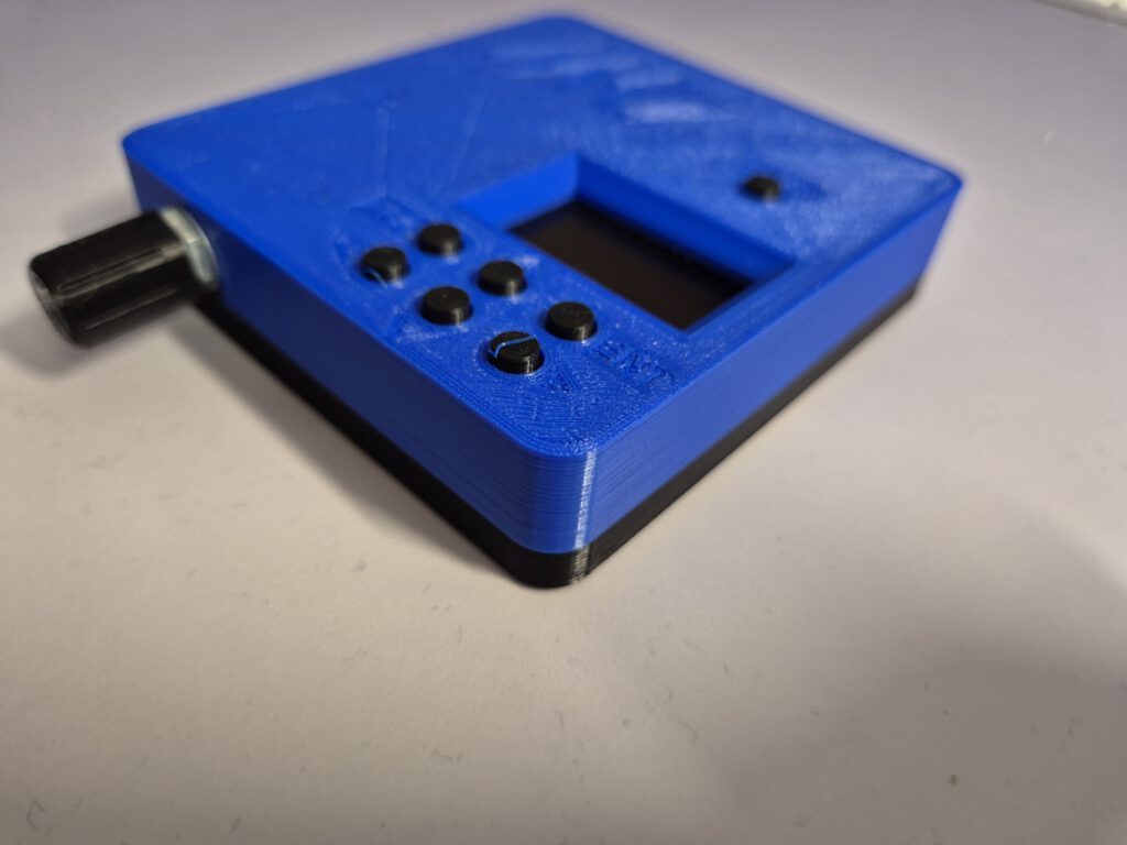
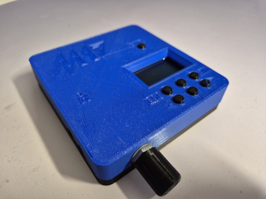
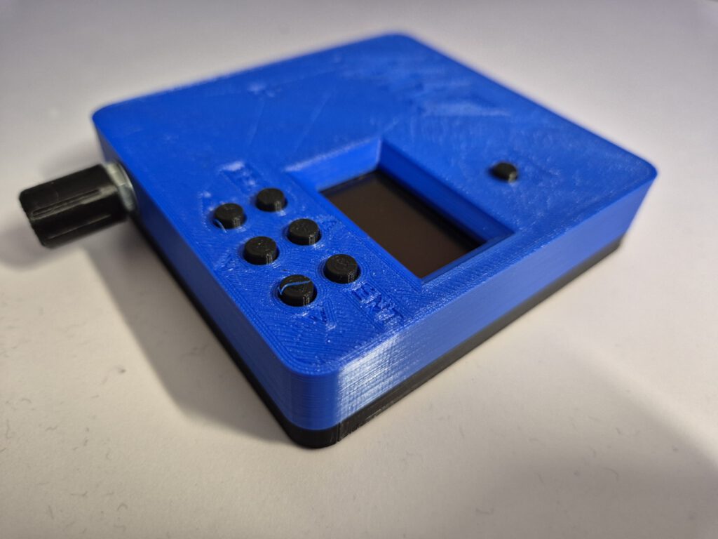
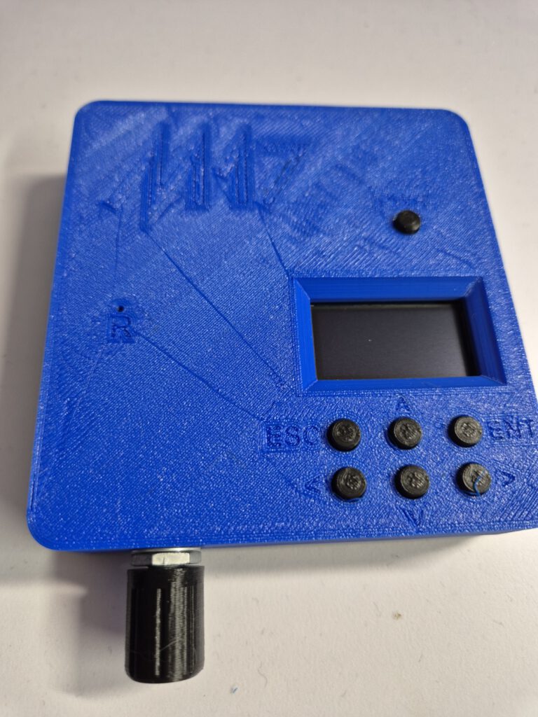
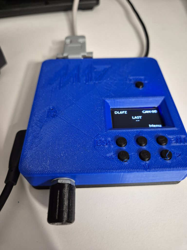
Happy me! Today both my Module17 arrived from China and the OLED Display module from Amazon. Coincidentally both on the same day. So in parallel to 3D printing the case, I build , flashed and tested the Module17 and a proper cable on my Yaesu FTM-6000. It worked really well! Here are the first pictures, I will post more pictures when my case for this one is done.

For the case I chose a combination of “Royal Blue” for the top cover and black for the back-cover, the buttons and the volume knob:

Posted in Digital Modes (VHF/UHF), M17 | Comments Off on My new M17 Module17

Modifying the RT3S / MD-UV380 for M17

The OpenRTX M17 user-guide is pretty clear on how to do this mod, but these are my pictures of the modification I did earlier today:

20250102_192101

Image 1 of 11

Posted in Uncategorized | Comments Off on Modifying the RT3S / MD-UV380 for M17

A 100kw power amp :-)

Yesterday I visited the German Armed Forces Technology Museum in Koblenz; the Wehrtechnische Studiensammlung (WTS) This is an amazing place to visit, which I can highly recommend to anyone who has a passion for (millitary) technology.

To my surprise they had a new asset: a 100kw power amplifier, a Telefunken SV 6816/1, which was used to communicate with u-boats. It operates at 14 kht to 50khz and needs 2,5kw drive power 😉

I made some cool pictures, I never had seen a 100kw amp before, so I was quite impressed!

20241230_123359

Image 1 of 11

Posted in Uncategorized | Comments Off on A 100kw power amp :-)

Yaesu FTM-400D Repair

I’ve been eyeing the Yaesu FTM-400D for quite some time. A friend of mine had one installed in his car, and I was impressed by its true dual-band functionality, the sleek display, and its 9k6 data connection.

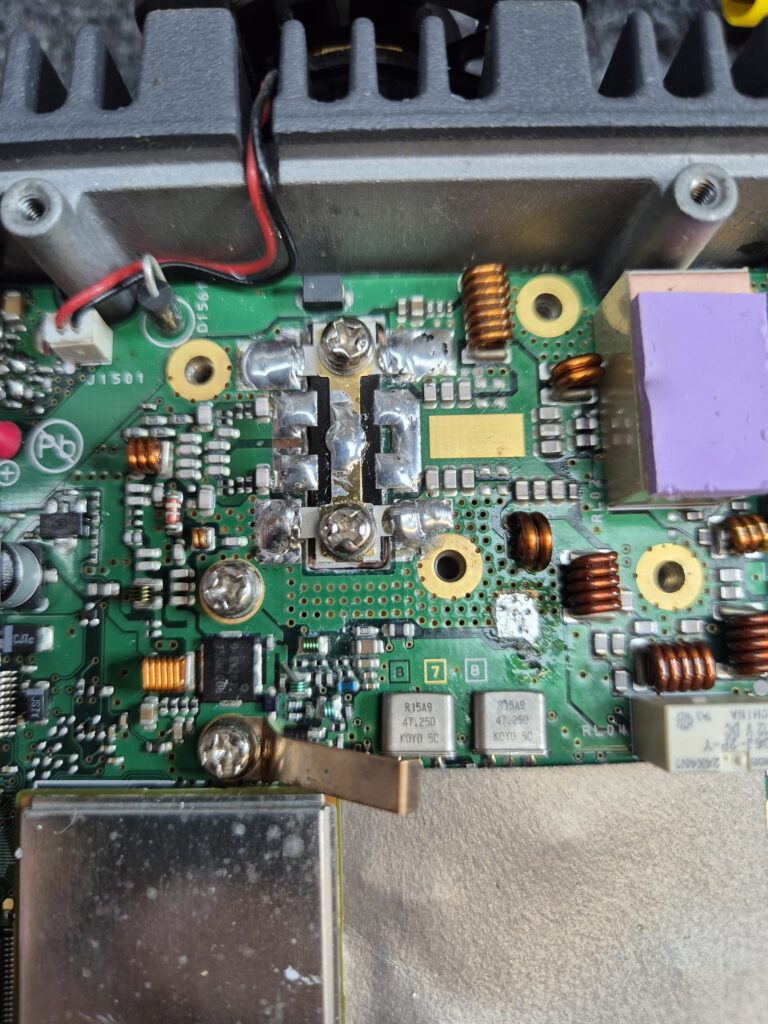
Since these models are no longer available for sale, I managed to find a used, defective unit on eBay. The fault description seemed straightforward, and I was about 90% certain that the issue lay with the final stage transistors shorting the radio. I purchased it at a reasonable price, and it arrived today.

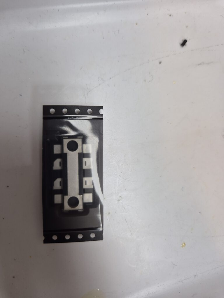
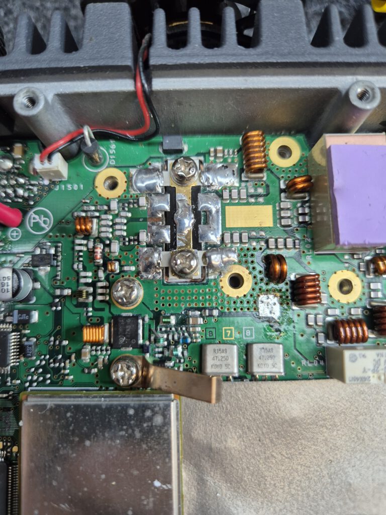
Initially, the radio wouldn’t power on. However, after removing the finals dual-MOSFET (an RD70HUF2), the unit powered up and operated flawlessly.

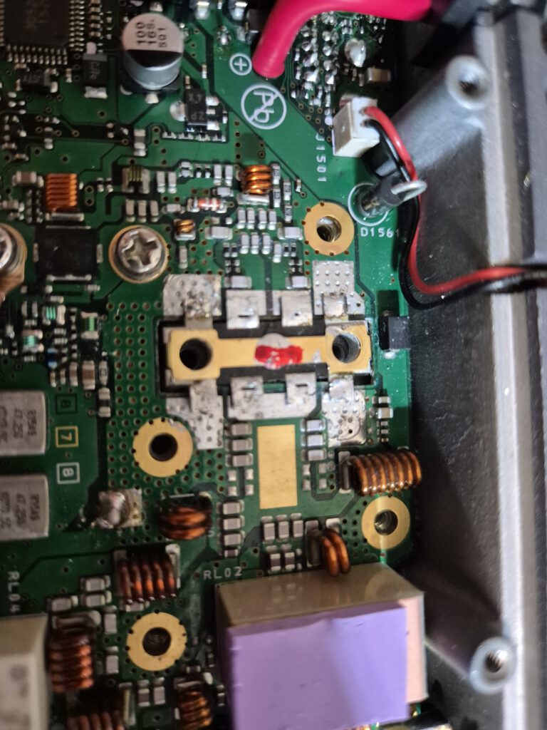
While I wait for the replacement finals chip to arrive, I thought I’d share some photos of the ongoing repair process. A big thanks to the team at Funk24 for stocking the part and ensuring fast shipping!

Special shoutout to Heinz HB9EKH for his incredible report detailing how to repair an FTM-400D. It was immensely helpful:

https://hb9be.ch/images/berichte2023/yaesu-ft-m-400-d.pdf

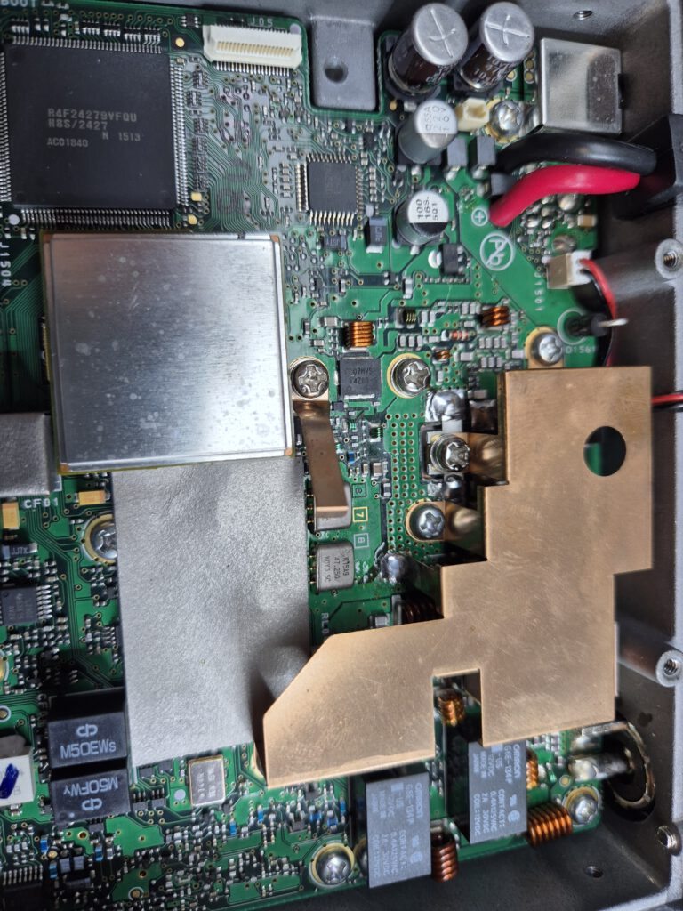
Here are my own first pictures:

Update: the new RD70HUF2 arrived and I finished the radio repair:

Posted in Yaesu FTM-400D | Comments Off on Yaesu FTM-400D Repair

M17 Experimenting

I finally had time to get M17 working and do some first experiments. Please have a look at my dedicated page on how this is working out!

Posted in M17 | Comments Off on M17 Experimenting